Modified Files:
src/perspective.cpp
Validation Files:
Depths of Field: scenes/camera/bokeh, scenes/camera/teapot
Lens Distortion: scenes/camera/bokeh
Chromatic Abberation: scenes/camera/teapot, scenes/camera/camel
Implementation
The depth of field implementation follows PBRT book's Projective Camera Models. The lens distortion follows Mitsuba 1 implementation. The chromatic abberation is designed by myself to approximate physcial effect based on Len's Maker Law and measured index of refraction for different light wavelength.
Depth of Field
The key difference between ideal pinhole perspective camera and thinlens camera is that the lens is no longer infinitely small, so during the ray tracing, the ray shot from the film will have direction offset after passing the thin lens (except it passes the center of the lens). To implement this effect, for a fixed film pixel, we uniformly sample the entry point on the spherical thin lens. For determining the direction of ray passing through this entry point, we apply the focal distance theorem and compute the intersection point between focal distance plane and the ray passing the film pixel and the lens center, then the light direction for that lens entry would be point to that intersection point.
In the implementation, two new properties are introduced: thin lens radius and lens focal distance. Only the object on the focal distance will be the most clear, and with increased radius, the object away from the focal plane will become more blurry.
Lens Distortion
Lens distortion effect is approximated by shifting 2D pixel place towards its corresponding location in distorted image. The equation relating the distorted images and the undistroted images is
$$r_{undistorted} = r_{distorted} + kc_1 r_{distorted}^2 + kc_2 r_{distorted}^4$$
Now we need to compute \(r_{distorted}\) from this non-linear relation, as suggested by Mitsuba 1, newton optimization is performned to approximate the correct values with limited step number of 5. Once we compute the shifting coefficient, we can modify the 2D film pixel place and use the new location to generate ray. This algorithm can also be performed directly on the rendered 2D image.
Chromatic Abberation
In physical camera model, chromatic abberation happens because lens have different index of refraction for different light wavelengthes, thus resulting the minor direction differences after a light passes through the lens.
Instead of approximating chromatic abberation effect in an artistic way in which color layouts drift more as the pixel is far away from the image center, I approximate this effect in a physical way. For thin lens, according to this website, the focal length of a lens can be determined by index of refraction and the curvatures of lens two sides.
$$\frac{1}{f} = (n-1)(\frac{1}{R_1} + \frac{1}{R_2})$$
In the formula, \(n, R_1, R_2\) are index of refraction, radii of the two-sided curvature respectively. Since lens curvature is fixed, once we can obtain the index of refraction for different light wavelength, we can derive the relative ratios of focal length for different light wavelength. I found a precisely measured IoR on this website.
With Gaussian Equation:
$$\frac{1}{f} = \frac{1}{z'} + \frac{1}{z}$$
where f is lens focal length for particilar wavelength (e.g. blue), z' is distance from lens to film (e.g. near_clip), z is focal distance for particular wavelength, I can compute the focal length \(f_{blue}\), and together with the ratios from len's maker laws, \(f_{red}\) and \(f_{green}\) are also computed. Then, the three focal distances \(z_{red}, z_{green}, z_{blue}\) can be computed by gaussian equation.
With three different focal distances, I do channel-wise sampling. Each time the sampleRay() is called, one of three RGB channels are randomly selected and the ray direction based on wavelength-specific focaldistance is sampled and the following procedure is similar to depth of field. Because we choose only one channel, the sampling weight needs to be modified (e.g. if red is selected, the weight is changed from [1.0, 1.0, 1.0] to [3.0, 0, 0]. This will cause colorful noise, but the result will converge as long as sampling number is enough.
During the validation, I found the it's time-consuming to find ideal parameters (z' and lens raidus) to illustrate effects. As the final goal of using the lens maker law and gaussian equation is to compute different focal distance for three light wavelength. I also add support for bypassing the physical formula and mannually overriding focal distance for three colors, this makes the effect more controllable.
Validation
Depth of Field
I validate depth of field on bokeh scene and teapot scenes.
The bokeh scene consists of an array of small spherical area light sources. The light array is in front of the camera and the distance is 70. Below is rendered by original perspective camera.

When the depth of field is activated, with lens focal distance as 30 (less than 70), the image becomes blurry as lens radius is increased. With lens focal distance as 110 (greater than 70), the image becomes bluarry as well as lens radius is increased. However, the blurriness for near objects are higher than far objects. This effect conforms to the PBRT's circle of confusion curves.
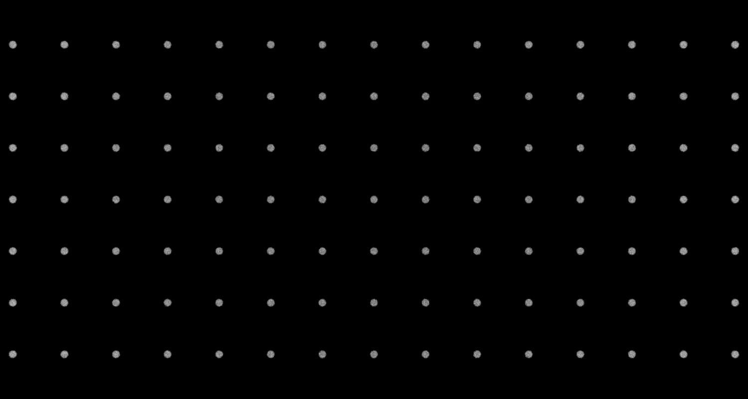
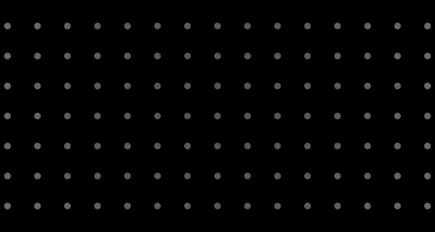

Depth of Field Effect (near object)
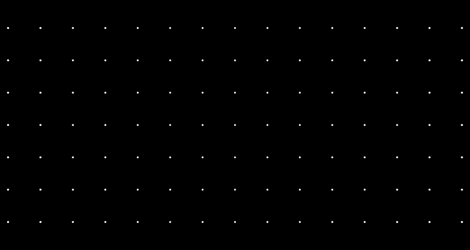
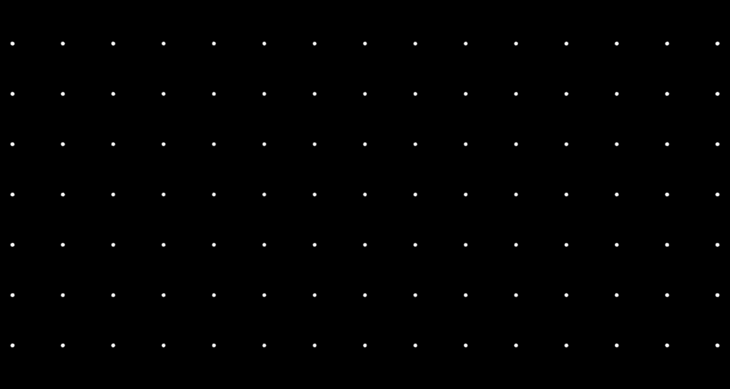

Depth of Field Effect (far object)
In the teapot scenes, with increased radius, the objects not at the focalDistance plane become more blurry.
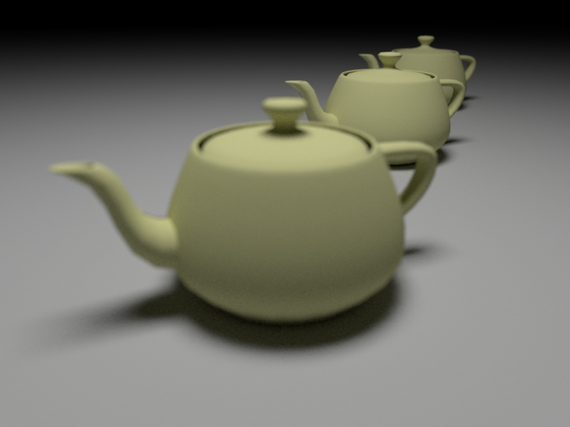
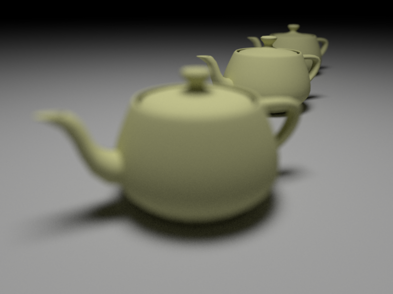
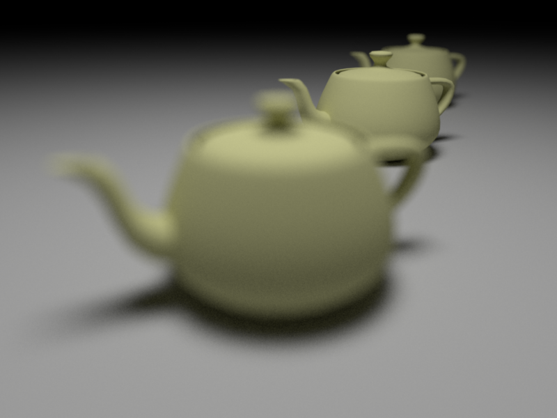
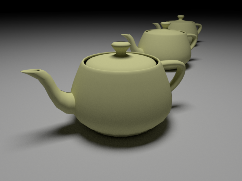
Depth of Field (Teapot)
Lens Distortion
In distortion model, the sign of \(kc_1\) mainly controls the barrel distortaion (negative) and pincushion distortion (positive).
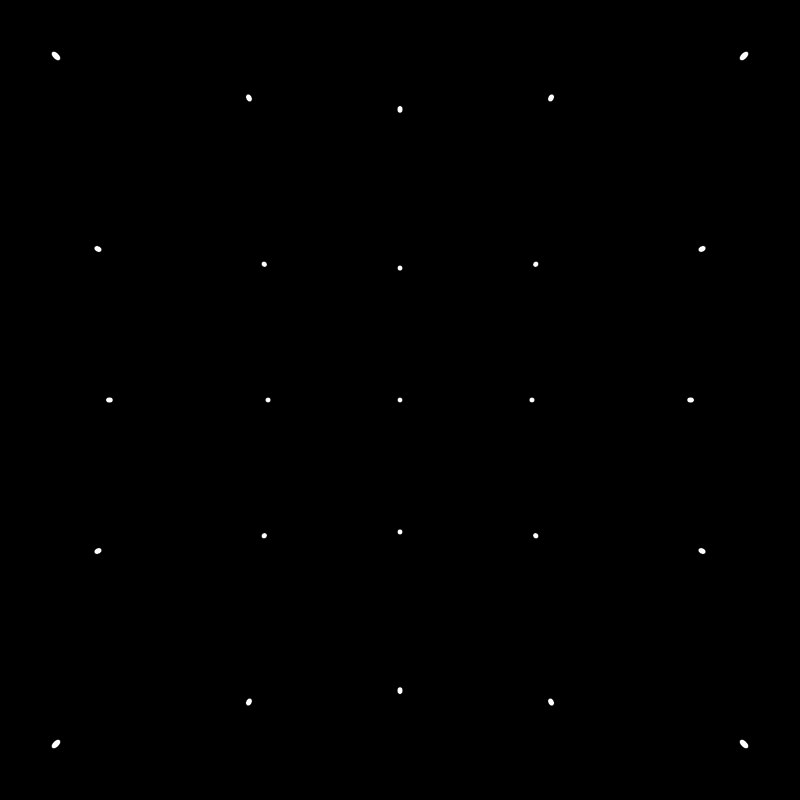
Distortion KC1=0.2, KC2=0.2
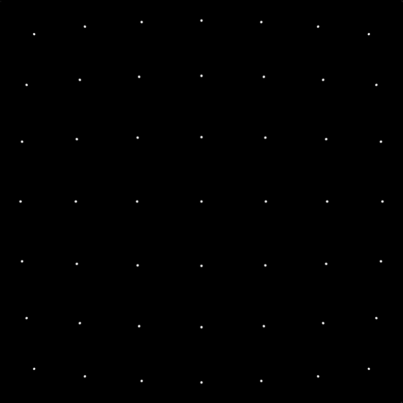
Distortion KC1=-0.07, KC2=0.0
Chromatic Abberation
Our implementation provides two interfaces to control the abberation.
The first one is more physical. By specifying \(z'\), focal distance for blue wavelength \(z_{blue}\), and index of refraction for three lights (if necessary), the system will derive the other two focal distance \(z_{red}, z_{green}\) based on lens maker law and gaussian equation. This interface requires more parameter tunning to get reasonble focal distance.
The second one bypasses the physcial formula, you can directly override focal distance for three wavelenth \(z_{red}, z_{green}, z_{blue}\).
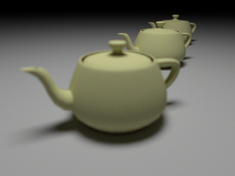
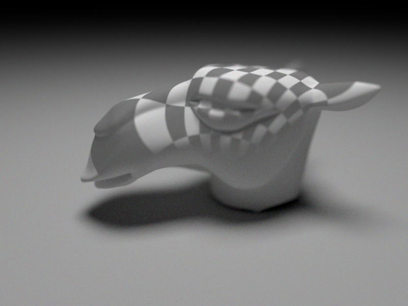
The first example is based on the first interface, in which at the cup lid of the first teapot where exists high contrast, the color layouts are not aligned. The second example is based on the second interface and shows the similar effects.
Note: this chromatic abberation implementation is based on depth of field (lens radius is not zero), this also meets the physical law that the pinhole camera will not have chromatic abberation effect.
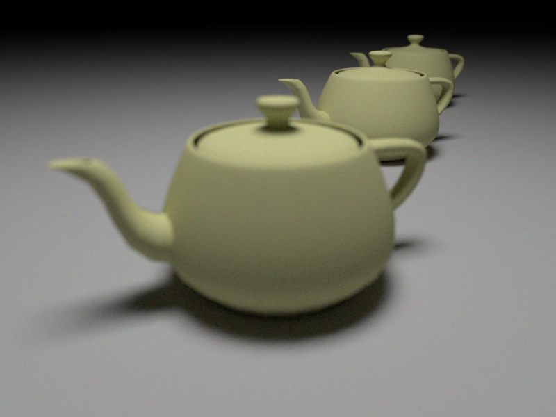
Chromatic Abberation (by lens maker law)
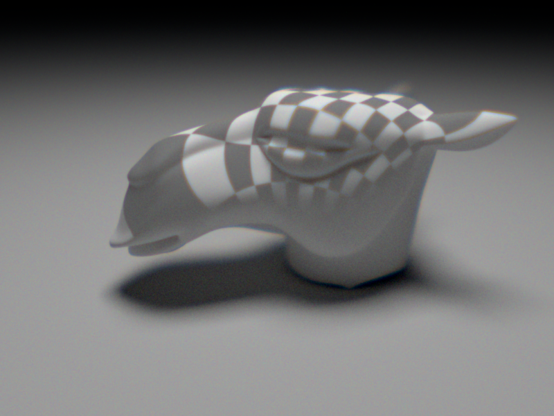
Chromatic Abberation (by mannual channel-wise focalDistance)